Nitrogen assisted alternatives to high pressure injection molding of large pieces are explored- Structural Foam, Counterpressure, Gas Assist, and External Gas Molding. Plastic flow and resin shrinkage are considered.
There is something about bubbles of nitrogen gas in molded plastic that assists with the process. Nitrogen gas is really a choice of convenience since it comprises about 85% of air. So commercial Nitrogen is produced by screening out Oxygen. The injection molding process is very susceptible to Oxygen which promotes resin-burning and degradation.
Looking first at the conventional Injection Molding process, the filling stage of the molding process is when the empty space in the mold cavity becomes the molded article. This is why designing the molded piece with uniform wall thickness is very important. Variations in thickness cause filling rate variation and therefore an increase in stress and cosmetic problems. With this perspective, we can visualize each of the assisted processes during the critical filling and packing stages. Since the foam and gas processes are nothing more than hybrid injection molding processes, it is logical that injection molding be the starting point of understanding the process basics.
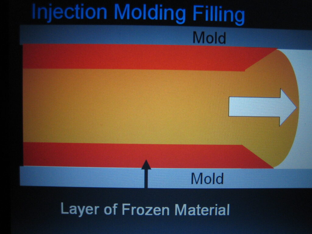
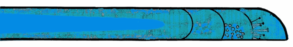
The first figure represents a cross section through the mold at the filling stage. Molten plastic is flowing from left to right, from the injection point location toward the end of flow. A leading edge forms the flow front of molten plastic. The essential point of this illustration is that skins are formed on the cool mold surface thus encapsulating the melt flow. With the filling stage, the difficulty is to inject all the resin to the end of flow prior to skin closure.
The second important concept is resin shrinkage. The transformation from melt temperature to ambient causes the spacing of molecules in the polymeric chains to become closer or tighter packed. In semi-crystalline or highly symmetrical molecular chained polymers, this volumetric shrinkage can be 20% or higher. In more randomly oriented chains or amorphous resins, this shrinkage is in the range of 5%.
Injection molding attempts to compensate for this shrinkage through an extended packing phase, which pushes more resin into the mold as this shrinkage occurs. The obvious problem is skin freeze-off, which isolates areas away from the gate. From this we can understand why solid injection molded parts often show signs of high stress.
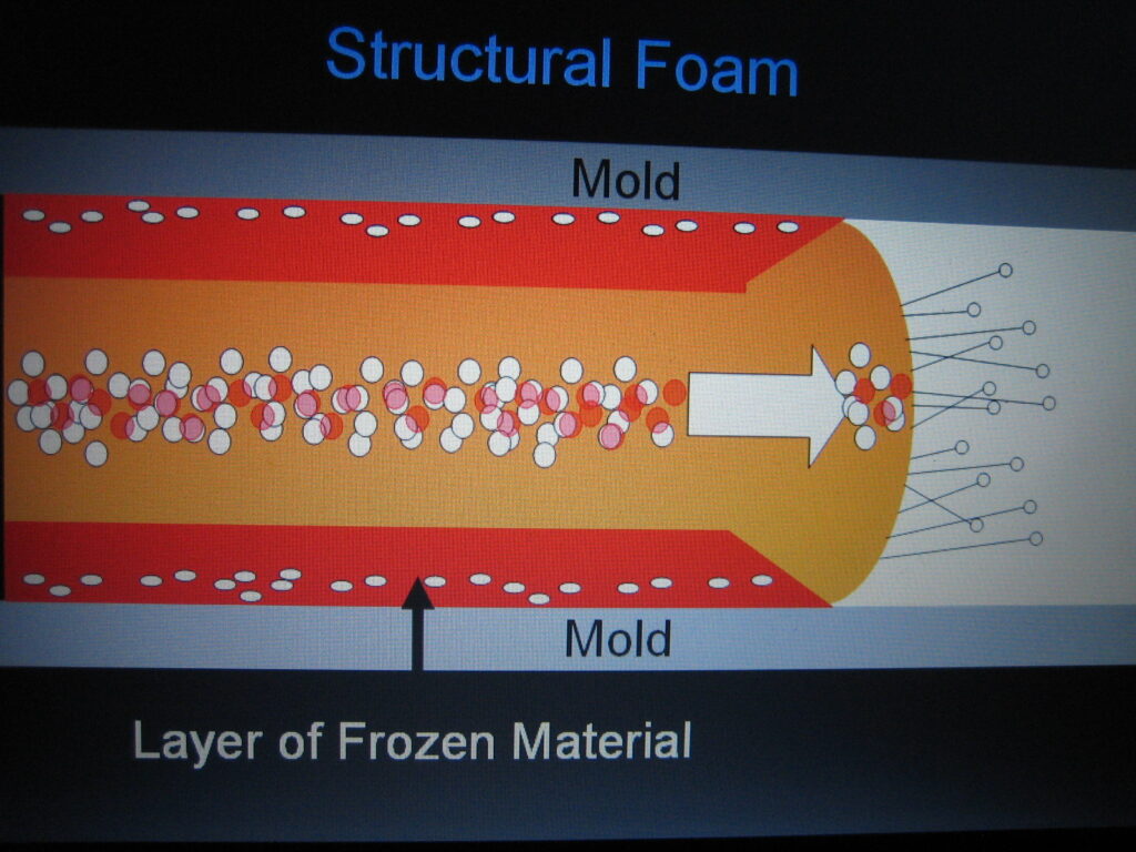
The next figure illustrates how structural foam compensates for flow and shrinkage with two major changes. There is a thicker wall section (often 2x) and a blowing agent, which is added to the molten plastic in the molding machine. The thicker wall allows an easier flow of a low-pressure short shot. In the later stages of filling, the blowing agent actually provides injection pressure on the flow front. The foam serves as an internal cushion for shrinkage and a stress reliever.
The draw back to structural foam is the surface finish of the molded article. During the critical filling stage, the blowing agent is escaping through the flow front and becoming trapped between the mold surface and the skin of the part as it is formed – resulting in a condition called “swirl”.
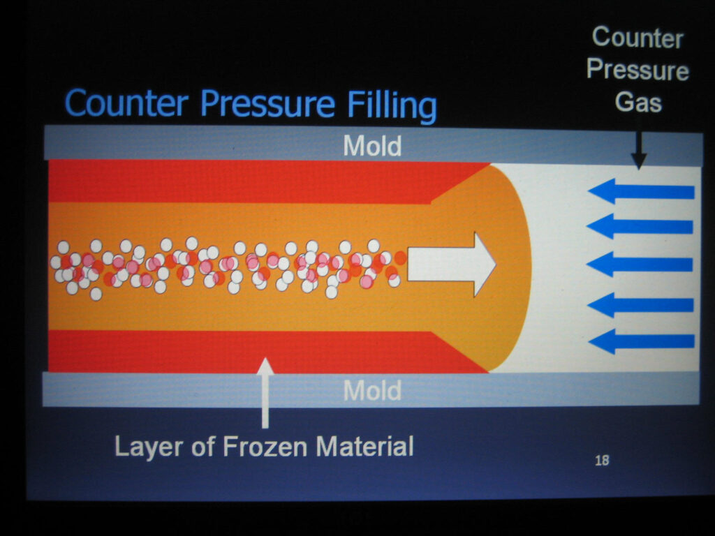
The figure illustrates counterpressure structural foam, which was invented as a method to eliminate “swirl”. This goal is accomplished by applying a resistance pressure (nitrogen gas) against the flow front, which is enough to keep the blowing agent in solution in the polymer melt and behind the flow front. This is accomplished by a pressure tight mold and special gas pressure and timing sequences on the molding machine.
Counterpressure structural foam succeeds in eliminating swirl and still maintains low stress through internal foaming but at the cost of the thicker wall of structural foam, and therefore, higher weight. This is compensated by greater physical properties.
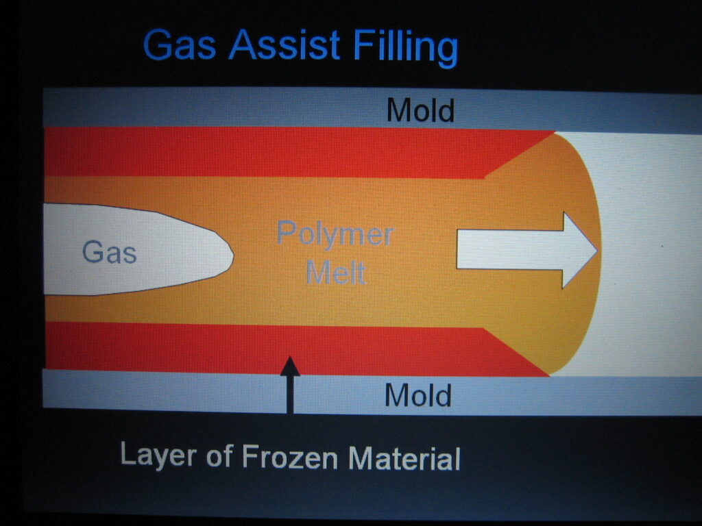
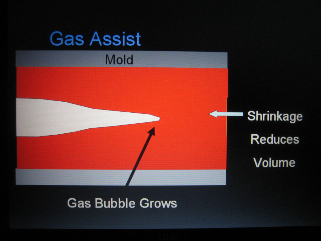
The next figures illustrate gas assist during the filling and packing stages. This shows how gas assist Gas assist stream helps with resin filling injection molding is capable of producing thin walled parts with low stresses by incorporating a stream of gas (usually nitrogen) within the polymer melt to enhance flow and compensate for shrinkage. With this process, the part designer becomes the process engineer as well. His placement of ribs and wall thickness determines the location of the gas passages, which are like in-part manifolds for material flow. Gas assist packs the mold after resin injectionProperly designed rib patterns can facilitate thin wall (1/2 that of structural foam) gas assist parts two ways. The ribs will become flow enhancers and when cored out with gas they become shrink compensators. The rib pattern then adds to overall part stiffness, overcoming the stiffness loss of thin walls. The figure on the right shows how the gas packs during the shrinkage phase. The gas bubble actually penetrates into the solid sections.
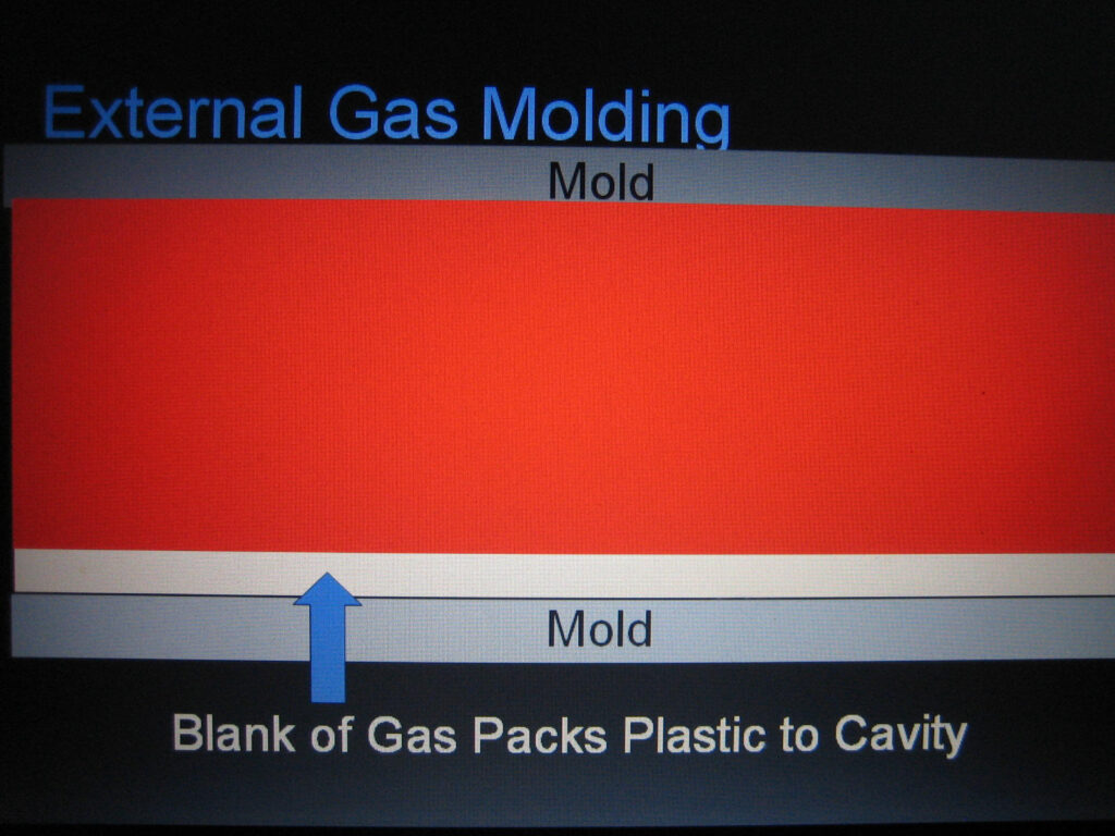
External Gas Molding (EGM) is shown on the left. Plastic fills the mold with normal injection molding methods but gas is injected afterward to compensate for shrinkage. The gas is injected from the face of the core and forces itself between the mold surface and the skin of the plastic as the molded part shrinks. This uniform packing pressure produces a low stress molded part capable of shorter cycle times. Clamping requirements seldom exceed 0.5 – 1.0 tons per sq. in.
Flow Length Considerations and Limits
To give a sense of relative flow of each process data in the following table is presented. The flow length ratio will depend on process conditions and part geometry and is intended for comparative analysis and rule of thumb. The ratio shown is the flow length divided by wall thickness and is useful in determining clamp tonnage requirements. The data is based on flow from any one injection nozzle. Multiple injection points will decrease the flow length, the L/T ratio, and therefore cavity pressure. Depending on the process and equipment there could be the need for a hot runner system in the mold.
| PROCESS | WALL | POLYPRO | H.I.P.S. | ABS | P.CARB. |
|---|---|---|---|---|---|
| Injection Molding | 3mm | 130 | 100 | 85 | 75 |
| Low Pressure SF | 6mm | 200 | 160 | 140 | 120 |
| Co-Injection SF | 5mm | 185 | 145 | 125 | 105 |
| USM/Exp.Mold SF | 3/6 | 130 | 100 | 85 | 75 |
| Counterpressure SF | 5mm | 175 | 150 | 130 | 90 |
| Gas-Assist Thick | 6mm | 200 | 160 | 140 | 120 |
| External Gas | 3mm | 138 | |||
| Inj. Compression | 5/3 | 185 | 145 | 125 | 105 |