Measuring In-Mold Pressures with the External Gas Molding Process (2006)
Jim Hendry, Brian Brookshaw, and Kamal Vinning – Cinpres Gas Injection
Steve Ham – Steve Ham Plastics
Abstract
External Gas Molding (EGM) is an emerging new method of injection molding. One of the main claims of the process is drastically reduced packing pressures allowing low clamp tonnage and reducing molded-in stresses. In-mold pressure sensors are placed in a special test mold to monitor pressure at critical stages of the process. EGM is compared with conventional injection molding and is correlated with clamp tonnage. Two resins are evaluated in the experiments; PC/ABS and TPO.
Background
External Gas Molding (EGM) has become recognized as a method of eliminating sink marks on injection molded parts. Previous papers by the authors have discussed the process basics and design guidelines to fully utilize the capabilities of the EGM process. Now we have data from ongoing studies that further illustrate the benefits of the technology. Lower packing pressure of EGM enables much lower clamp tonnage yet provides improved packing. Measuring the pressures in the mold cavity demonstrates the packing effectiveness. The pressure traces also provide plastic shrinkage during the cooling phase and how it can be controlled with EGM. Improved cooling translates in reduced overall cycle time and payback options.
The EGM Process
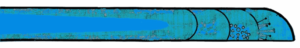
The EGM process is based on injecting gas at controlled pressures and timing at one surface of a mold after plastic has been injected completely into the mold. The gas forms a micro thin layer between the plastic and the adjacent mold surface. Thereby the gas is used as a medium for applying uniform pressure to the plastic forcing it against the opposite mold surface as it cools, shrinks, and solidifies precisely replicating the mold surface. See Figure 1.
Stress-free molding is achieved by allowing more shrinkage to occur inside the closed mold. With conventional molding much of this shrinkage occurs after the part is removed from the mold. Imagine five sided box one foot square with one inch side walls. Even with a low shrink resin such as PC there is .062”, 1/16”, or 1.5mm of shrinkage that must occur to the part. According to the laws of physics most of this shrinkage will occur after ejection from the steel core. With EGM, much of the shrinkage still occurs outside of the mold but there is no orientation stress so the part shrinks uniformly and flat. This accounts for EGM’s typical cycle time improvement of 15%. The molded parts have very little stress so the cooling cycle does not have to be extended on warpage-oriented designs.
EGM is a true low pressure injection molding technology. Clamping tonnage rarely exceeds one ton per square inch. Since there is little or no high pressure packing phase there are energy savings in two ways. The machine hydraulics have less work less to achieve high pressure clamping because the plastic is at lower pressure. Secondly the lower injection pressures require less work on the injection side of the system. The same logic is true with electric molding machines because the amount of work is still reduced.
Alternative methods of sealing to prevent escape of gas are necessary as either integrally molded seals or mechanical seals. These options are illustrated in Figure 1. As the incoming gas ribbon separates the molded plastic skin away from the mold surface on one side of the mold, the plastic is pushed into the opposite mold half. The ribbon of gas moves toward the parting line and to avoid pressure loss there has to be a seal. Special provisions have been devised to seal the mold cavity such as integral seals and “O” ring seals. Patented sealing expertise is included in the technology package that comes with the purchase of the EGM license.
With EGM, gas is injected at one or more positions from gas injection pins. Typically the gas injectors are located on the ejection side of the mold and can be incorporated without interfering with waterlines or ejector pins.
The process can be used with most injection molding technologies and materials as a stand-alone accessory to the basic I. M. machine. EGM can be used as a short shot method for low pressure molding. It can be used as a full shot molding with or without packing. In applications with excessively thick ribs (ie. aspect ratio of 3-10) EGM can be used in conjunction with internal gas injection. It works very well with counterpressure molding either foamed or solid.
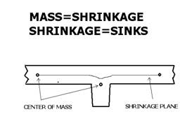
Center of Mass Considerations
The concept of “center of mass” brings further enlightenment to resin shrinkage and the resulting sink marks. Consider a centerline running through the mid section plane of the exterior skin or nominal wall section. Any molding orientation is evenly split between the two halves and shrinkage will be uniform. When a rib intersects the nominal wall section there is a change in the center of mass and therefore a shrinkage concentration. The result is sink marks. Sink marks are indicators of molded in stress resulting from non-uniform shrinkage.
With the EGM process the center of mass is moved much closer to the center plane of the wall section. Often plastic at the base of the rib is displaced into the shrinkage vacuum.
Description of the Test and Methods
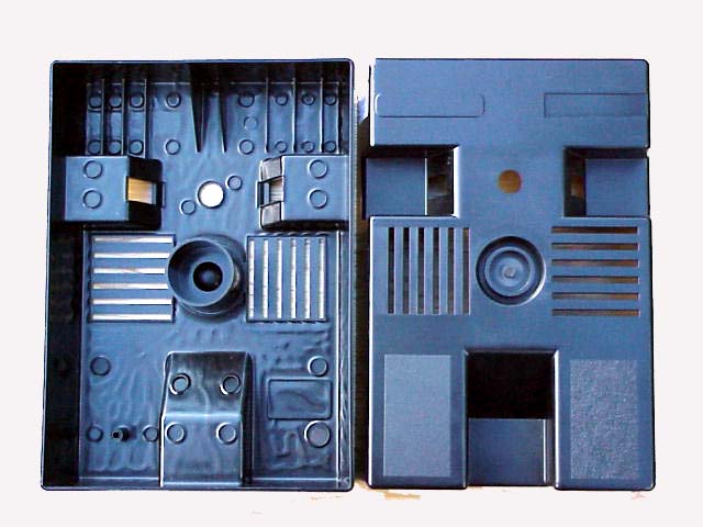
Rectangular shaped test component measuring approximately 280mm X 190mm X 50mm with apertures and various ribs of different heights and thicknesses. The ‘A’ surface of the mold has gloss, mat and grained finishes.
Component wall thickness is 2.5mm.
The mold is a test mold to evaluate the effect of EGM with different materials and processing conditions.
The mold is designed with 6 EGM gas injection nozzles and 1 gas pin located in boss.
The locations of EGM gas nozzles and isolated areas between ribs served with a singe EGM gas nozzle in each area.Tool has integral seals around ejector pins, inserts and apertures: ‘O’ ring seal are used at the base of each EGM gas nozzle.
Pressure transducers, one transducer in each half of the mould, are fitted into the mold to record cavity pressure from plastic pressure and gas pressure, mounted away from the gate area on the weld line.
Plastic injection is from cold sprue gate; feeding directly on to the component.
Five second injection delay is reflected on the pressure trace graphs.
Injection time 4.0 seconds; Pack time 4.0 second- Injection only
Cooling time 41 seconds
Gas delay 10 seconds
Gas pressure 150 bar
Gas hold on time 10 seconds
Mold temperature 70° C
Melt 260° C
EGM component weight 319 grams in PC/ABS material. When injection molded the pack cushion added 2 grams.
Connecting pipe work to the gas injectors is kept short as possible.
Pressure Trace Results and Discussion
Several pressure traces were created during the test trials. Of particular interest in this analysis are the pressures exerted on the molten plastic after the injection phase and during its shrinkage or cooling phase. During conversations with the author, Dr. Brown at the University of Bradford’s IRC of Polymer Science and Technology said that when injection molding a component of 2.5mm wall thickness, after ten seconds of cooling, there has been enough shrinkage to pull the plastic away from the cavity wall surface. Her statement is based on ultrasonic measurements of the injection molding process, a methodology in which she has collaborated. Her comments are verified by the pressure traces of this study. Asahi Chemical performed studies of dozens of molding operations, revealing that 70% of a typical mold’s cooling capability is in the cavity half and only 30% in the core half.
The pressure traces show effectiveness of gas packing pressure verses plastic injection packing pressure; extending well beyond ten seconds. Further, comparing cavity side pressure verses core side pressure is very insightful into the movement of plastic during the shrinkage phase. The blue line represents the gas pressure and the red line reflects the resulting plastic pressure against the cavity wall. The gap between these lines indicates the elasticity of the resin. A rigid material (amorphous plastic) transmits the gas force more effectively than a more elastomeric resin.
This series of graphs show cavity pressure in blue and injection pressure in red.
Conventional injection molding pressure traces show that within ten seconds, there is virtually no packing pressure getting to the mold surface. It further shows that as soon as the packing pressure falls off, there is a vacuum of plastic shrinking away from the cavity. Core half pressure is slightly elevated reflecting the pressure of shrinkage down on the core of this four sided box. In this scenario, the mold cooling is only at 30% of capability because the cavity has very little contact with the plastic.
By adding EGM to the same scenario, the difference is vivid. The first indicator is packing pressure effectiveness. The pressure trace shows packing pressure is exerted to the end of the cooling phase allowing more stress free and uniform shrinkage. The injection molding trace showed no pressure after ten seconds. The core side pressure is greater, as expected, since the gas pins are located in this mold half. The cavity trace is actually created by the pressure of the plastic in the mold being pushed from the opposite side. Predictably there is some loss of packing force but the overall effect is obvious. The plastic is being held in contact with the mold cavity for the entire cooling cycle to utilize 100% on the mold’s cooling capacity.
The EGM pressure trace with an amorphous material (PC/ABS) shows the differences of high shrink material verses low shrink material. The first indicator, packing effectiveness is similar and still impressive, but the close spacing of the two curves indicates nearly complete transfer of packing energy from the core side gas to the plastic in contact with the cavity face. The shrinkage induced stress will be uniform throughout the molded article. The cross over of the two lines occurs because of the material’s transition point holding the article in place along with the drop in gas temperature (and therefore pressure) on the core side. After a few seconds the lines meet again due to pressure equalization.
The EGM pressure trace from high shrinkage materials such as this TPO resin will show a gap between cavity and core pressures. EGM cavity packing effectiveness is lower for crystalline or high shrink materials. Transfer of packing pressure is adequate to maintain plastic to cavity wall contact through the cooling phase. High shrink materials will require more EGM induced plastic movement. This is accomplished with gas pressure profiles and both resin and mold temperatures.
Energy Savings
The University of Bradford (UK) has completed extensive research into energy consumption of various plastic molding processes and was the subject of his paper at last year’s conference. The results of this work indicate that regular internal gas assisted molding yielded 5% energy saving over conventional injection methods. EGM yielded an 8% improvement over conventional. This happens on both ends of the injection molding machine. There is less clamping tonnage obviously, but less conspicuous is the energy used by the injection unit during conventional molding’s packing/cushion phase. Further the study was able to determine true production output by comparing pounds per hour of shippable product. EGM showed an amazing 18% improvement over conventional injection molding. Dr. Dawson at Branford concluded that the energy savings might seem small but, over time, are very significant. He also felt that energy savings of EGM are out weighted by the saving achieved in both material reduction and more significantly cycle time.
Dimensional Stability Improvement
Improved dimensional stability of molded articles has been reported from industry. Two different hot plate welded polypropylene programs have seen drastic improvement of line scrap and robot rejects. During molding trials, two of the authors witnessed the reduction from 25% welding rejects to less than one half of one percent (.5%) simply by turning on the external gas. This is logical considering the reduction of molded in stress resulting from non-uniform shrinkage. A future study will measure dimensional accuracy versus cycle time on EGM versus conventional injection molding.
Conclusion
The measurement of in mold pressures has substantiated several claims of the EGM process. The data shows that EGM provides more effective packing than the traditional plastic cushion. The measurements show that EGM packing pressure is conveyed through the molten plastic to the cavity half of the mold. This is very advantageous since 70% of the molds cooling capability is from the cavity half, and the external gas pressure keeps the plastic in contact with the cavity wall through the entire cooling cycle. EGM’s lower in-mold packing pressures require less clamping forces and overall energy. Dimensional stability benefits from low cavity pressure because of reduced residual stresses of EGM moldings. The uniform packing pressure of the external gas results in uniform shrinkage and reduced molecular orientation.
This paper represents an on-going development of the EGM process. Future analysis will include part weight analysis and more pressure transducers in the torture mold with ultrasonic measurements during the molding cycle. The authors give thanks to Dr. Brown with the University of Bradford and Jan Czerski with Faraday Plastics.
March 2006.
Follow-On Work
Further research is underway examining the interaction of cavity temperature verses gas pressure. Substantial benefits have been observed with elevated cavity temperatures. As an example, recent testing showed faster cycle times with 150 degrees F and 1,000 psi gas pressure. Lower cavity temperature of 100 degrees F requires 1,500 psi gas pressure. Future research will explore how higher mold temperatures result is faster overall cycle time. (September 2009)
Closed loop methods are also under evaluation. EGM packing used in conjunction with counterpressure filling has the potential to achieve consistent plastic flow rate by communicating with the machine’s injection unit. (Oct. 2009)
Substantial development work is underway with full shot EGM. This method completely fills the mold with plastic and includes a brief machine packing pressure at which point the EGM gas takes over further packing when the machine pressure is no longer effective. (July 2009)
Key Words:
EGM
External Gas Molding
Gas assisted injection molding
Injection molding
Low stress molding
Reduced energy consumption
Ultrasonic measurements
References:
Jim Hendry, “Hydra-forming for Injection Molding” presented at the Molding ’92 Conference, March 23, 1992.
Jim Hendry, “E.G.M. External Gas Molding”, presented at the 30th Annual Structural Plastics Conference, March 15, 2002.
E. C. Brown, L. Mulvaney-Johnson, and P.D. Coates, of the University of Bradford, “Ultrasonic Monitoring of Gas Assisted Injection Moulding (GAIM)” presented at the 2004 ANTEC Conference sponsored by SPE.
Jim Hendry and Steve Ham, “Guidelines for Functional Design Utilizing External Gas Molding”, presented at the Structural Plastics 2004 Conference, March 22, 2004.
Dr. Andy Dawson of IRC in Polymer Science & Technology at the University of Bradford, “Energy Saving By the Use of Gas Assisted Molding” presented at the 2005 Structural Plastics Conference.
B. R. Whiteside, E. C. Brown, Y. ONO, C. F. Jen, and P. D. Coates, “Polymer Degradation and Filling Incompletion Monitoring for Micro-molding Using Ultrasound” presented at the 2005 ANTEC Conference sponsored by SPE.