STRUCTURAL PLASTICS- DESIGN FOR FUNCTION
Steve Ham
Steve Ham Plastics, Highlands, North Carolina
Abstract
A methodology in producing highly functional designs is discussed. The family of injection molding processes referred to as Structural Plastics offers product designers more design liberty with net-shape moldings. The inherent high cost of “plastics” is offset with highly functional and value added features. Functionality determines which process and resin should be specified through cost/benefit analysis.
Background
Product designers developing new products have a great opportunity in taking advantage of the latest technologies to insure a market success for their product. Indeed, the competition can be smashed right at the drawing board by creating a product with the lowest manufacturing cost while staying within the available tooling budget. The popularity of injection molding over recent years is a result of the designer’s growing demand for net shape moldings [1]. For the large part markets, variations of injection molding referred to as structural plastics (gas assisted injection molding and structural foam), have been developed to produce large parts under lower pressures. Plastic materials are more expensive than traditional materials such as wood and steel. The competitive advantage comes with the incorporation of functional details not obtainable in continuos shape fabrication. It is the conversion from raw material to final product in one step that drives this advantage. Techniques such as “design for manufacture” and “design for assembly” are based on the concept of parts consolidation and reduced assembly labor. In terms of design elements, the wall thickness has to be considered the backbone of the design, but the ribs and projections give the majority of function. The part designer has the task of sorting out the many resin/process options to produce the most functional and competitive option. “Design for function” is a procedure to facilitate the design of such products.
Design sequence
The selection of a given process has to be closely matched with resin specification. Hundreds of resin options coupled with dozens of conversion technologies result in an incomprehensible option list. In reality, a review of the market shows that certain resins team up with certain processes across a variety of markets. The following is the process selection/part design sequence of events:
- Value Analysis phase.
- Determine functional requirements.
- Design features into ribs and bosses.
- Determine wall thickness, molding process, and resin.
- Finalize design and details.
- The procedure described in the remainder of this paper is different than traditional approaches. The procedure is best for new designs or total product redesigns where a “clean sheet” or “blank screen” is unrestrictive.
Value Analysis
The initial and most creative phase of product development is to evaluate every purpose of the product. An itemized list of “essential” and “desired” features is developed. Detailed cost and lead-time are estimated for each feature and compared with the value it creates. If actual costs are undeterminable, budget estimates are created. Total projected lifetime revenue and market window for the product is then compared with the cost for all the various elements of the design. Cost benefit can be established for each feature. Every piece that attaches to or is attached to an item is evaluated. This includes hardware, labor, and overhead costs. Software supplier companies have programs that are very effective if the blackboard method is too cumbersome. An iterative process considers the various options and determines preferred design relative to budget impact. In the final analysis, cost benefit criteria determine the features of a given product.
A proven methodology of value analysis has been developed by the VAAST Group over the past over fifty years [2]. Some of the elements of this value added philosophy have been applied to product development as follows.
- Clear the Slate- Remove all preconceptions of the design and start with a clean sheet, a blank screen, or a clear slate. All options are open. Take a view from higher ground such as the customer perspective.
- Gather Information- Determine every possible need of the application along with every possible feature it could offer. Evaluate competitive models with a similar list. Consider methods not available when the competition tooled-up. Search for trends in parallel products and markets. Consider that customer needs are constantly changing.
- Functional Analysis- The overall competitiveness of the product will be determined in this phase. Using the features list, analyze each in terms of function. Establish essential and desired functions then rate each in terms of application importance, performance, and cost. Look for and redevelop value mismatches such as high cost and importance with low performance or high cost and performance with low importance.
- Evaluation- Consider each function on a chart comparing total cost, lead-time, and value contribution. This is an iterative procedure considering each optional approach and judging the merits on the chart. The overall value and cost benefit will determine the desired approach.
- Implementation- During the remaining steps of the design process, continue to review and update the functional analysis charts.
Functional Design
With the list of features determined by fully developed functional analysis charts, the product designer creates a platform of functional details by determining the mating and mounting surfaces. The goal is net shape molding, which will yield the final product, or something close, directly from the molding machine. Close dimensional tolerance from part to part allows for mounting details to be molded in place, even when assembly robots are used in subsequent operations. The desired material properties are determined at this phase based on overall stiffness, temperature, and impact requirements. Styling, shaping, texturing and overall appearance are unique to molded plastics. Weight reduction, impact resistance, and weather ability are considered. The unique properties of plastics can create value for a product through successful design.
Traditionally, the product designer establishes wall thickness early in the piece part design. The classic Glenn Beall design philosophy adds projections and depressions to a backbone of uniform wall thickness [3]. “Design for function” actually has wall thickness being determined later in the design cycle, after functional requirements establish ribs, bosses, and holes. Wall thickness will determine the molding process to a large extent. Greater thickness allows deeper and thicker ribs.
While one process may appear as a stronger contender, it cannot be confirmed until all the detailing is complete. Gas assist may have more ultimate potential for tall ribs but some designs require thicker walls, which is where structural foam provides more consistency.
Ribs, Bosses, and Holes
Determine ribs, bosses, and openings necessary to support the functional platform of mating and mounting surfaces. Overall stiffness is also considered in determining to the height of ribs. In order to anchor the functional platform of ribs, an internal wall surface is created. The overall thickness and outside surfaces of the nominal wall are determined later in the cycle. Most of the functional detail will come in the form of ribs.
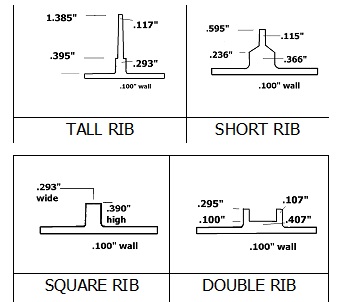
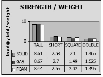
While the molding process will effect the strength of ribs, in general there is very little difference as proven by a series of technical papers entitled, “Who has the best ribs in town?” It was a multi-year evaluation of performance of four different injection molded rib designs in three different structural plastic molding processes [4,5]. The four rib designs represent many of the options the designer would use for the functional detailing.
The same ABS resin was molded in the structural foam, gas assisted injection molding, and traditional solid injection molding processes. While several properties were considered in the studies, the strength to weight findings summarize the results well.
The summary data shows that there is actually very little difference in performance (less than 4%) between the processes. What the data does not show is that the rib aspect ratios used in the test plaques are beyond the design limitations for solid molding injection molding. Structural foam or gas assist is often the only practical solutions to a challenging or highly functional rib design. The designer should allow the rib layout to achieve maximum function unencumbered. When maximum function is achieved rib design can be finalized.
Determine Wall Thickness/Process/Resin
Three elements are used as tools to determine wall thickness: aspect ratio, flow length, and gating options. The aspect ratio of rib thickness to wall thickness will range form .5 – 5.0, depending on the molding process. Analyze the rib layout and determine the rib aspect ratio being created and select the wall thickness and process best suited to the design.
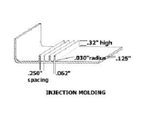
High-pressure injection molding has strict design guidelines for aspect ratio, often .5, which limit thickness and depth of ribs. On the other hand, gas assisted injection molding should have a rib aspect ratio of 3.0 – 6.0 to enclose the gas bubble and prevent gas fingering into the solid wall section. Wall thickness of more than 4mm is difficult with solid injection molding due to resin shrinkage.
Gas assisted injection molding has the benefit of increased profile ribs giving greater design flexibility for functional projections [6]. Gas assisted injection molding has been in the marketplace long enough to establish its pattern of applications. In less than ten years gas assist molding exceeded the size of the structural foam market.
The overlap between the processes is narrowing. While there are many successful thick walled gas assist designs, the process is best employed as a thin wall process for optimizing unit cost. Thin walls are strengthened with oversized ribs or types of projections which contain the entire gas bubble. Keeping the bubble contained within the rib allows the walls to be solid and therefore perform in a more predictable manner, which is important to highly optimized designs. Thick walled gas assisted parts will have randomly distributed gas bubbles, which can cause variation from part to part. Performance and appearance concerns arise from this variation. Structural foam is a more uniform and repeatable method for thick walled parts.
Structural foam has thicker walls, with foam compensating for resin shrinkage, thicker rib aspect ratios, and wall thickness variations. Neither solid injection molding nor gas assist does well with excessive wall thickness variation. Wall thickness design flexibility then seems to be the most important uniqueness of structural foam. It should be the first choice for designs requiring thicker wall (4mm-8mm) and/or wall thickness variation of up to 100%. Greater wall thickness translates to greater stiffness; often allowing lower cost resins to perform like engineering materials.
Consider the relative flow of the process selected from the following data. The format was initiated by Indra Baxi [7] and elaborated by the author and associates [8]. The flow length ratio will depend on process conditions and part geometry and is intended for comparative analysis and rule of thumb. The flow length ratio shown is the flow length divided by wall thickness (L/T). Consider flow ratio to determine molding process.
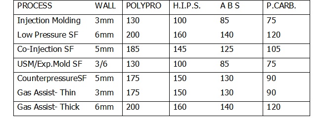
Note: Data is based on flow from one injection nozzle. Multiple injection points will increase the possible size of the molded part. Depending on the process and equipment, there could be the need for a hot runner system in the mold.
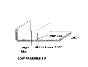
The flow length ratio (L/T) is also used to determine cavity pressure. The following example chart, from Uniloy Milacron, is for low-pressure structural foam [9].

Evaluate potential gating locations using the cavity pressure data. Remember that gate locations have higher stress levels and cosmetic issues. The clamp tonnage of the molding machine should be able to handle the cavity pressure. Dividing cavity pressure by a conversion factor of 2,000 will give the tonnage required per square inch of projected part surface. An example is an 800 sq. in. projected surface molded part with an L/T of 80 and 505 psi cavity pressure. It will need ¼ ton per square inch, and 200 tons of machine clamp tonnage. Adequate machine shot size but without excessive resonance degradation is another important consideration in machine selection criteria. When the gate locations are fixed, adjust ribbing and wall thickness if necessary for flow considerations.
Overall stiffness has to be reconsidered relative to the wall thickness, which effects stiffness by the power of three. Doubling wall thickness achieves 8 times the rigidity (2 X 2 X 2). The inherent stiffness of the resin is a factor. Adding fillers such as glass or minerals can increase the flexural modulus of the base resin.
If a thicker walled design is specified, the material specification should be re-considered. An example would be a solid polycarbonate part with a wall thickness of 3mm being replaced as a structural foam part at a 6mm wall in polystyrene. The actual material cost can favor the thicker walled option.
Final Considerations
Weld lines are the final mechanical element to review in the procedure. Recognize that they are generally the weakest area of the molding. Wherever there is an opening there will be a weld line. Multiple gate locations create further weld lines. Weld line issues may require going back to the Functional Design phase for proper resolution.
Cosmetic requirements are a major consideration in many applications. Molded-in color and texture give plastic moldings a unique advantage. Lower costs and environmental impact along with improved durability offer value to an application. Each of the structural plastic molding processes has cosmetic limitations. Injection molding will show sink marks and flow lines. Gas assist tends to have gloss variation and hesitation lines. Low-pressure structural foam has “swirl” or grooved flow marks. Review design for possible problems.
Dimensional tolerances are a benefit of the structural plastic processes. The ability for net shape molding allows molded in features with tight tolerance that would require secondary machining in most other methods of manufacture. Automation and robotics are feasible with the part-to-part consistency achievable with most resins and processes of the structural plastics family.
External reinforcement is also a practical solution when beam stiffness is needed on a highly detailed and functional part. Simple part configurations, which require great stiffness, are often better left to inherently flat materials such as sheet metal and wood, which offer the greatest stiffness to cost. Look for composite performance from multiple component systems. An example is a piece of glass providing stiffness and a plastic bezel providing impact resistance. Consider the functional performance of the assembled unit.
Conclusion
“Design for Function” follows a logical procedure to collect and analyze data, which leads to products that are highly functional and designed for value. By analyzing the needs of the application, the functional details are determined. Ribs and bosses form a functional platform, which is then attached to the wall section best suited. Using aspect ratios and flow length data, the wall thickness and resin are determined. The final design details such as cosmetics, tolerances, and specifications complete the design task. This sequence differs from the industry norms but is well suited for innovative designs.
Key Words
- Structural plastics design
- Structural foam molding
- Gas assisted injection molding
- Injection molding design
- Functional design
References
- Robert Clearman ”Replacing Traditional Materials in Durable Goods with Engineering Plastics”. Challenging the Status Quo in Design Retec Chicago, IL – March 23-25, 1993 sponsored by SPE.
- Value Analysis & Systems Technology Inc. (VAAST). Web site at www.valueanalysis.com
- Glenn Beall, Design for Injection Molding
- Peter Grelle, “Solid vs. Gas vs. Foam: Who Has the Best Ribs in Town?” World Class Injection Molding Retec sponsored by The Society of Plastics Engineers, September 25-27, 1994
- Peter Grelle, “Solid vs. Gas vs. Foam: Who Has the Best Ribs in Town? Part Deux.” Structural Plastics 96 Conference sponsored by the Structural Plastics Division of SPI, March 31- April 3, 1996
- Matthew E. Sawyer, “Application of Gas Injection Technology” available from Cinpres Ltd.
- Indra R. Baxi, “Future Trend: Gas Injection Technology”. Eighteenth Annual Structural Plastic Conference, April 2-4, 1990, sponsored by SPI.
- Stephen Ham, Richard Hotaling, David Speiser, “A Comparative Part Cost and Application Study in Multiple Processes from a Molders Perspective.” 23rd Annual Structural Plastics Conference April 2-5, 1995 sponsored by SPI.
- Uniloy Milacron- Technical literature- “Structural Foam and Structural Web Molding” by Ed Hunnerberg.
- About the Author
- Stephen Ham is a graduate of Western Carolina University holding a Bachelors of Science degree. In 1973 he joined the structural foam industry during its infancy and participated in its rapid growth, while at a leading structural foam custom molder. He served in a variety of marketing, sales, and engineering positions. During this period, he was involved in literally thousands of structural foam feasibility studies. In 1997, he formed his own consulting company to focus on the successful application of structural plastics. He has contributed to SPI’s Structural Plastic Division and is the 1994 recipient of the annual Recognition Award. He is a member of SPE and is active with the Product Design and Development Division serving as its Chairman. Mr. Ham is the author of the chapter on structural foam in Irv Rubin’s “Handbook of Plastics Materials and Technology”, published by Wiley and Sons. He has been an instructor in previous SME seminars and courses.
This white paper was prepared for and presented at the annual ANTEC Conference staged by the Society of Plastics Engineers. It is the organization for plastic professionals: